Sunday, November 6, 2022

Series Circuit Calculations

What is a Series Circuit?


A Series Circuit is a circuit in which the current has a single path to flow.

Calculating a Series Circuit:


We can calculate voltage, resistance and current across a Series Circuit using Ohm's law & then check the calculations using a multimeter. Here are the steps:
  • Draw the Series Circuit showing voltage and resistors.

  • Draw a table with columns for all the resistors, voltage, impedance (current) and their total.
  • First, calculate the total resistance using the following formula:
            Rt = R1 + R2
  • Next we will calculate the total current using Ohm's law.
            It = Vt/Rt
            The answer will be in Amperes. We can multiply the answer by 1000 to make it milliamperes.
  • Calculate the voltage across each resistor using Ohm's Law:
            V1 = I1 x R1 
  • Calculate current across each resistor using Ohm's Law:
            I1 = V1/R1

Conclusion:

In a Series Circuit, the Voltage is divided but the Current remains the same.

Verification:

You can test your calculations by using a multimeter on a real circuit or it's simulation in Tinkercad.

More Information:


Parallel Circuit Calculations


What is a Parallel Circuit?


A Parallel Circuit is a circuit in which the current has multiple paths to flow.

Calculating a Parallel Circuit:


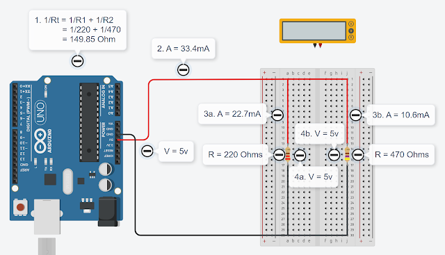
We can calculate voltage, resistance and current across a Parallel Circuit using Ohm's law & then check the calculations using a multimeter. Here are the steps:
  • Draw the Parallel Circuit showing voltage and resistors.

  • Draw a table with columns for al the resistors, voltage, impedance (current) and their total.
  • First, calculate the total resistance using the following formula:
            1/Rt = 1/R1 + 1/R2
  • Next we will calculate the total current using Ohm's law.
            It = Vt/Rt
         The answer will be in Amperes. We can multiply the answer by 1000 to make it milliamperes.
  • Calculate current across each resistor using Ohm's Law:
            I1 = V1/R1
  • Calculate the voltage across each resistor using Ohm's Law:
            V1 = I1 x R1

Conclusion:

In a Parallel Circuit, the Current is divided but the Voltage remains the same.

Verification:

You can test your calculations by using a multimeter on a real circuit or it's simulation in Tinkercad.

More Information:


Tuesday, October 18, 2022

Ohm's Law

Ohm's law


                        V = I R


In this formula V  is voltage and its measured in volts, I is impedance which is also called current is measured in amperes and R is resistance which is measured in Ω (ohm).

Voltage (V)

Voltage is the potential difference between the negative and positive terminals of a battery.
It shows how much power or energy electric charge has to flow from one terminal to other.

Current (I)

Current is how much electric charge flows/second.

Resistance (R)

Resistance is anything that is stopping the electric charge from flowing.

Calculating Voltage 

To calculate voltage we have to know current and resistance.
                V=IR

Calculating Current

To calculate current we have to know voltage and resistance.
                I=V/R

Calculating Resistance

To calculate resistance we have to know voltage and current.
                R=V/I

Measuring voltage

To measure voltage we place the multimeter on the positive and negative terminals or on each side of the electronic component.

The amount of voltage been taken by each component is called voltage drop.

Measuring current

To measure current we break the circuit and place the multimeter in between the circuit.

Measuring resistance

To measure resistance we take out the component from the circuit and then measure it by a multimeter.


Fun Fact
While we normally show current flowing from positive to negative terminal in a circuit, the electric charge actually flows from negative to the positive terminal!

Click to watch my video of this Blog on YouTube:

Wednesday, October 12, 2022

Lecture 3. Arduino IDE

 The interface

  1. The check mark is used to verify the code if there is an error.
  2. The arrow button uploads the code to arduino.
  3. 'New' opens a new window to code.
  4. 'Save' saves the code as an Arduino sketch.

There are 2 functions when you open a new sketch.

  1. void setup() {}
  2. void loop() {}

Tinkercad.com

"TinkerCAD" uses the same C++ code as Arduino IDE . Whatever block code you pick in TinkerCad, it'll also be translated to text code.

The setup function and pinMode

In 'setup' function, we tell our program to engage an Arduino pin by writing the function 'pinMode(,)' & in its parameters, we tell which pin number to engage &  if we want to take its output or input from Arduino. Output means to take voltage out of Arduino while we use 'input' when we attach sensors because they are giving pulse to Arduino.

The loop function and digitalWrite

This function goes on repeat.
Inside the loop function, we place another function called 'digitalWrite'  in its parameter, we tell the program that the pin we engaged for Input or output. do we give it a high voltage or low voltage.
After executing the code, the code loops again & again.

Please watch the video for this Blog on YouTube:
https://youtu.be/a4PSFc3nCss

Sunday, October 9, 2022

Using a Multimeter

I powered Arduino with USB cable from my Laptop and I connected 5v of arduino to the positive rail of a breadboard and I connected GND of Arduino to negative rail of the breadboard. Next I put an LED on the breadboard and I connected 470 ohms resistor to the anode of LED so it doesn't blow up and I put another LED and its anode is going from the first LED's cathode and the second LED's cathode is going to negative rail.

First I measured resistance by tu4ning the Multimeter knob to resistance. To do that, I put 3 resistors  of 458 ohms, 968 ohms, and 2.12 kilo ohms on the breadboard, out of my circuit and measured it by the multimeter.

Secondly I measured current going across the LED by inserting the multimeter inbetween the circuit and turning the multimeter knob to DC Amperes. The current going from the resistor to the LED was 2.18 mA.

Lastly I measured voltage. To measure voltage going through a component we put the component between the positive and negative terminals of the multimeter. The voltage going through the arduino is 5.13 volts,  1.07 volts going through the resistor, 1.95 going through the first LED and 1.98 volts going throght the second LED.

Q. How can I measure current, voltage and resistance accross a circuit?
     Ans. We can measure current by a multimeter

Click this link to check the video:


Wednesday, October 5, 2022

Single LED with Arduino

I powered Arduino with USB cable from my Laptop. I used a wire from 5v of arduino uno to the positive rail of a breadboard. Then I connected 470 ohms resistor with positive rail of the breadboard, so the LED doesn't blow up (LED needs 20.00 mA else it will blow up or not work). I connected the anode of a LED with the resistor. Then I connected the carhode leg of LED with the negative rail of the breadboard. Finally I connected GND of Arduino to negative rail of the breadboard. That's it, the LED lights up!

Series Circuit Calculations

What is a Series Circuit? A Series Circuit is a circuit in which the current has a single path to flow. Calculating a Series Circuit: We can...